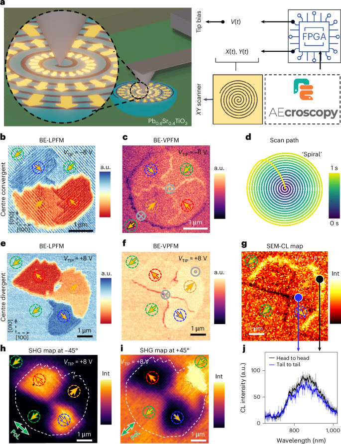
By precisely controlling the movement of the piezo-positioner during scanning, it becomes possible to guide the probe along any predetermined scan path, enabling the creation of specific topological configurations, not possible using existing scan paths (Supplementary Fig. 5). As shown in the setup sketch in (Fig. 3a), we achieved such precise control by integrating a commercially available AFM system with a field programmable gate array (FPGA), controlled externally with custom Python programs (AEcroscopy36). In the experiments described below, we prepare the surface via standard raster scanning with a biased tip, aligning the polarization in a specific direction over a large area (~100 μm2). This process creates a ‘blank slate’ in one of the four stable super-domain configurations (I−, I+, II− and II+; Supplementary Fig. 6).

a, An illustration of the experimental setup used for the measurements: AEcroscopy Python package controls an FPGA, which inputs the generated signals (tip bias V(t), X piezo bias X(t) and Y piezo bias, Y(t)) to the AFM controller to autonomously perform the previously Python-designed experiment. b, BE-LPFM piezoresponse (cantilever long axis parallel to [100] crystallographic axis of the sample) of the written centre-convergent structure. c, BE-VPFM piezoresponse of the written centre-convergent structure; the grey cross and dot in a circle indicate the direction of the out-of-plane components for head to head and tail to tail. d, A spiral tip trajectory for the writing of the centre-convergent structure, starting the path at the centre and with a total duration of 1 s. e, BE-LPFM piezoresponse (cantilever long axis parallel to [100] crystallographic axis of the sample) of the written centre-divergent structure. f, BE-VPFM piezoresponse of the written centre-divergent structure; the grey cross and dot in a circle indicate the direction of the out-of-plane components for head to head and tail to tail. g, SEM-CL map of the same centre-divergent structure. h, An SHG map of the same centre-divergent structure with the polarizer at −45° (see green arrow). i, An SHG map of the same centre-divergent structure with the polarizer at +45° (see green arrow). j, Single SEM-CL spectra at head-to-head and tail-to-tail super-boundaries in the locations indicated by the black and blue dots in g, respectively. VTIP is the writing bias used to generate the structure. Int, intensity of the cathodoluminescence (CL) signal.
For example, we demonstrate the use of a spiral-scan trajectory (Fig. 3d)—characterized by a radial slow-scan direction and tangential fast-scan motion—to nucleate and stabilize centre-convergent and centre-divergent structures using negative (Fig. 3b,c) and positive (Fig. 3e,f) tip biases, respectively. This approach unlocks the combination of the four distinct super-domain orientations into a stable configuration, with the in-plane super-domain dipoles orientated inwards and outwards, respectively, featuring charged internal (and peripheral) super-boundaries. Band-excitation lateral PFM (BE-LPFM) reveals the polarization alignment of the generated structure, finding it is not governed by the radial (slow-scanning) direction, since the super-domains are orienting the polarization anti-parallel (same direction, opposite sign) to it. As a result, super-domain alignment contrasts with expectations for raster scanning, where a parallel alignment leading to a centre-divergent structure would be expected for a negative bias scan that begins at the centre and traverses outwards radially. Instead, a centre-convergent structure is stabilized. Conversely, a positive bias, anticipated to produce a centre-convergent structure under the same scanning direction, results in a centre-divergent structure.
Interestingly, the corresponding band-excitation vertical PFM (BE-VPFM) images (Fig. 3c,f) reveal an asymmetric vertical contrast at certain super-boundaries. Head-to-head super-boundaries exhibit a positive vertical electromechanical response, while tail-to-tail super-boundaries exhibit negative response, suggesting a local polarization tilting towards positive (and negative) out-of-plane direction at these charged locations, respectively. The lack of conductive-AFM contrast at the super-boundaries (Supplementary Fig. 7) indicates that these charges observed by KPFM are not mobile (Supplementary Fig. 8).
To explore the structural reorganization effects, we conducted correlative SHG and SEM-CL measurements on the same structures. SHG maps (Fig. 3h,i) reveal quadrant-specific excitation in centre-divergent structures, dictated by the orientation of polarized light adjusted at ±45°. This approach enables precise mapping of local polarization, complementing BE-LPFM data and providing deeper insight into generated super-boundaries. At a polarizer angle of −45° (Fig. 3h), only quadrants aligned with the incident light’s polarization yield measurable SHG signals; at +45° (Fig. 3i), complementary quadrants display SHG responses along with background. Notably, the +45° image exhibits an enhanced SHG response at head-to-head peripheral super-boundaries, indicating dipole alignment along the material’s [110] axis, alongside observed out-of-plane polarization tilting.
SEM-CL measurements over the same area reveal nanoscale variations in colour centres and local polarizations (Fig. 3g), highlighting imbalanced head-to-head (bright) and tail-to-tail (dark) super-boundaries. The interaction of a focused-electron beam with a ferroelectric material is influenced by luminescent centre concentration and localized charge, shaping electron beam interactions. The near-infrared cathodoluminescence spectra peaked at 860 nm (Fig. 3j) maintains consistent shape but varies in emission intensity, suggesting changes in radiative recombination efficiency or light-emitting species concentration. In PSTO, charged defects, such as vacancies and compensating ions, are presumed to asymmetrically stabilize frustrated super-domain configurations. Positively charged head-to-head super-boundaries promote accumulation of charged defects associated with efficient light emission, resulting in stabilized luminescence that favours carrier trapping and boosts radiative recombination processes in these areas.
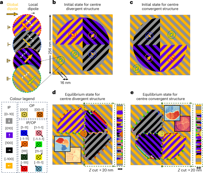
To deepen our understanding of the stability and polarization reorientation at the frustrated super-boundaries (Supplementary Figs. 10 and 11), we performed phase-field simulations (Fig. 4). We started with initial structures (Fig. 4b,c) mirroring the super-domain configurations observed before (Fig. 3) and, subsequently, allow these structures to relax to an equilibrium state under a tensile strain of 2% (Methods). The simulations reveal that the initial configurations indeed relax towards stable arrangements through polarization reorientation to stabilize the high electrostatic/strained super-boundary locations, which are energetically less favourable. Specifically, the tail-to-tail super-boundaries at the centre of the centre-divergent structures generate a polarization rotation towards the out-of-plane, downward direction (that is, dark orange, centre of Fig. 4d). Conversely, at the centre of the centre-convergent structure, the head-to-head super-boundaries rotate the polarization towards the out-of-plane, upward direction (that is, light green, centre of Fig. 4e), in agreement with the BE-VPFM contrast found experimentally (Fig. 3).

a, The nanoscale arrangement of the global (orange) and local (black) ferroelectric dipoles in the in-plane directions for the four different super-domains. The colour legend indicates the three-dimensional polarization direction for the phase-field structures. b, The initial state used in the phase-field modelling for the centre-divergent structure. c, The initial state used in the phase-field modelling for the centre-convergent structure. d, The equilibrium state obtained in the phase-field modelling for the centre divergent. The inset describes the experimental BE-LPFM and BE-VPFM of the centre-divergent structures of Fig. 3. The Z-cut cross-section across the whole film along the dashed green line is shown on the right. e, The equilibrium state obtained in the phase-field modelling for the centre-convergent. The inset describes the experimental BE-LPFM and BE-VPFM of the centre-convergent structures of Fig. 3. The Z-cut cross-section across the whole film along the dashed green line is shown on the right. The colour legend indicates the three-dimensional polarization direction for the phase-field structures in-plane (IP) and out-of-plane (OP).
Likewise, in all the centre-divergent and centre-convergent structures written on a uniform ‘blank slate’, we find a highly frustrated peripheral super-boundary in one of the four quadrants where the super-domain of the ‘blank slate’ collides with the anti-parallel super-domain present in the structure (top-right super-boundary in Fig. 4c and bottom-left super-boundary in Fig. 4e). In those cases, we also observe the polarization rotation inducing an out-of-plane component of the polarization vector but in this case with additional in-plane component also present (red and light-blue walls in Fig. 4c,e, respectively), which we hypothesize is responsible for the enhanced SHG signal (Fig. 3i). This reorientation also induces the formation of ‘sawtooth’ faceted super-boundaries to minimize the electrostatic/elastic energies (Supplementary Figs. 10 and 11). The simulations indicate that while most of the polarization arrangements are homogeneous through the thickness of the film, the small out-of-plane canting is most prominent near the film surface (cross-sections in Fig. 4c,e).
Overall, we determine that it is possible to stabilize out-of-plane polarization at the super-boundaries of PSTO through the right accumulation of elastic stress and electrostatic energy and that this material stabilizes upwards out-of-plane polarization to accommodate the head-to-head super-boundaries and, conversely, downward polarization to accommodate the tail-to-tail super-boundaries. Moreover, we suggest that indeed, the in-plane local polarization rotation steps necessary to switch the a1/a2 domains may happen through an intermediate out-of-plane rotation37,38, which would be mediated by the tip vertical electric field, thus becoming the dominant agent of the in-plane super-switching (Supplementary Fig. 11).
As such, we can now revisit the hierarchical super-switching mechanism. The spiral scan starts in the central point where the vertical electric field nucleates a local out-of-plane polarization (upwards for negative bias and downwards for positive bias) surrounded by a convenient super-domain arrangement with artificial super-boundaries (head-to-head for negative bias and tail-to-tail for positive bias). In the absence of a scan path, these nucleation centres become unstable due to their small area-to-boundary ratio and quickly relax when scanned over (Supplementary Fig. 12). Spiral scanning stabilizes these centres, expanding the super-boundaries via out-of-plane intermediate switching by creating a1/a2 stripe domains, which are as parallel as possible to the fast-scan direction (tangential) and align appropriately with the nucleated super-domain configuration, generating a global orientation anti-parallel to the radial direction. Therefore, we speculate that in this case the stabilized final polarization arrangement is dictated by the sign of the initially nucleated domain in the centre and not by the slow-scan direction, challenging the trailing electric field theory30,39.